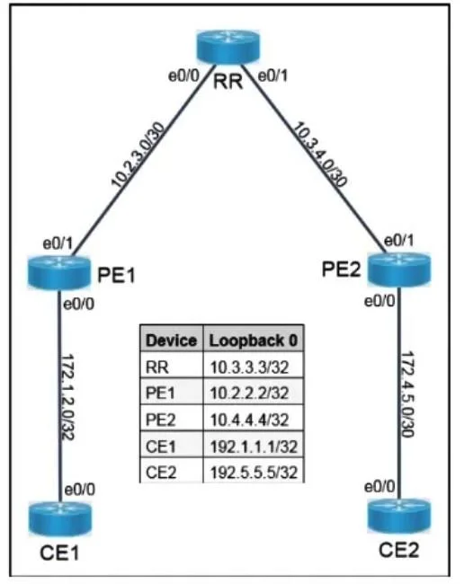
SIMULATION 5 Guidelines This is a lab item in which tasks will be performed on virtual devices. • Refer to the Tasks tab to view the tasks for this lab item. • Refer to the Topology tab to access…
The correct answer is B. Configure router ospf 1 under the global configuration on R2. Note: The simulation context describes an MPLS L3VPN/BGP scenario, but the multiple-choice options all relate to OSPF - these appear to be from two separate questions merged together. The explanation below addresses the OSPF answer choices as presented. --- Option B is correct…
Core Routing
Question
SIMULATION 5 Guidelines This is a lab item in which tasks will be performed on virtual devices. • Refer to the Tasks tab to view the tasks for this lab item. • Refer to the Topology tab to access the device console(s) and perform the tasks. • Console access is available for all required devices by clicking the device icon or using the tab(s) above the console window. • All necessary pre-configurations have been applied. • Do not remove any existing configurations from the devices, only those necessary to make the appropriate changes required to fulfill the listed tasks. • Do not change the enable password or hostname for any device. • Save your configurations to NVRAM before moving to the next item. • Click Next at the bottom of the screen to submit this lab and move to the next question. • When Next is clicked, the lab closes and cannot be reopened. Topology Tasks CE1 and CE2 are IPv6 Customer Premise Equipment of two customers that communicate with each other through the MPLS L3VPN core comprising Provide Edge PE1, PE2, and route- reflector RR. Perform the below configuration and verification tasks as noted. 1. Troubleshoot and modify RR to allow PE1 to receive VPNv4 routes from PE2 and vice versa. 2. Troubleshoot the PE routers to ensure the CEs can ping each other via their Loopback 0 addresses. The initial configuration with IP addressing has been completed. Do not change the configurations except to fulfill the abovementioned tasks. Apply the solution with the minimum configuration to allow additional PEs if needed. Answer: 1. On RR - make it a VPNv4 route-reflector for the PEs Under BGP on RR, in the VPNv4 address-family, configure the PE neighbors as route-reflector clients (keeping the existing neighbors and update-source as they are), for example: router bgp <SP-AS> address-family vpnv4 neighbor 10.2.2.2 route-reflector-client ! PE1 loopback neighbor 10.4.4.4 route-reflector-client ! PE2 loopback exit-address-family If not already present, neighbor <PE-lo0> activate and neighbor <PE-lo0> send-community extended must also be under address-family vpnv4 2. On PE1 and PE2 - fix VRF import/export so CE loopbacks are reachable end-to-end On both PEs, in the VRF used for CE1/CE2, ensure that the same route-target value is used for both import and export so that VPNv4 routes are imported into the correct VRF on the remote PE. For example (names and values adapted to the actual config): ip vrf CUST-A rd 65000:1 route-target export 65000:1 route-target import 65000:1 (or adjust the existing route-target commands so that PE1 and PE2 share at least one identical import/export RT). The RR receives all VPNv4 routes from the PEs, but without the route-reflector-client configuration in the VPNv4 address family it does not reflect those routes between the PEs. Making the PE neighbors RR-clients (and ensuring they are activated with extended communities) allows the RR to advertise each PE's VPNv4 routes to the other, so PE1 learns CE2's VRF routes and PE2 learns CE1's. Even with VPNv4 exchange working, CE loopback reachability between sites depends on the PEs importing the received VPNv4 routes into the correct VRF. That import is controlled by route- targets; both PEs must use a common route-target value for export and import. Once the RTs match, each PE imports the other's CE routes into the same VRF, and the IPv6 (or IPv4, depending on the lab) loopback prefixes of CE1 and CE2 become reachable across the MPLS L3VPN core, allowing successful ping between their Loopback0 interfaces.
Exhibits
Options
AConfigure ip ospf network non-broadcast under Gi0/0/1 on R2
BConfigure router ospf 1 under the global configuration on R2
CConfigure no passive-interface under Gi0/0/1 on R1
DConfigure prefix-suppression under the global configuration on R1
How the community answered
(43 responses)
A
7% (3)
B
58% (25)
C
26% (11)
D
9% (4)
Explanation
Note: The simulation context describes an MPLS L3VPN/BGP scenario, but the multiple-choice options all relate to OSPF - these appear to be from two separate questions merged together. The explanation below addresses the OSPF answer choices as presented.
Option B is correct because if R2 has no OSPF process configured at all, no OSPF adjacency can form regardless of any other interface-level settings - enabling router ospf 1 globally is the foundational prerequisite that makes everything else possible.
Why the distractors are wrong:
A (ip ospf network non-broadcast on R2's Gi0/0/1) changes how OSPF handles hello/DR elections on that segment, but is irrelevant if OSPF isn't even running on R2 - and non-broadcast mode would typically hurt adjacency formation unless manually configured peers are added.
C (no passive-interface on R1's Gi0/0/1) would only matter if R1 was suppressing hellos on that interface; the problem described is on R2, not R1.
D (prefix-suppression on R1) hides transit link prefixes from LSAs - a valid optimization, but it doesn't prevent adjacency formation and has nothing to do with R2 missing an OSPF process.
Memory tip: Think of it as "you can't tune an engine that doesn't exist." Always verify the OSPF process (router ospf <pid>) exists on a device before troubleshooting interface-level OSPF parameters - missing the global process is the most overlooked misconfiguration on exams.