
800-150 · Question #84
Drag and Drop Question Drag and drop the failures from the left onto the responsible devices in the MDS field-replaceable unit on the right. Answer:
The correct answer is power supply modules; fan tray assembly; line card slots 1 and 2; supervisor modules; line card slots 5, 6, and 7. MDS Chassis FRU Placement Explanation This question maps Cisco MDS 9000-series (likely the MDS 9507, a 7-slot chassis) field-replaceable units to their physical positions on a chassis diagram. The numbered positions (1–5) represent labeled locations on the chassis, ordered…
Question
Drag and Drop Question Drag and drop the failures from the left onto the responsible devices in the MDS field-replaceable unit on the right. Answer:
Exhibit
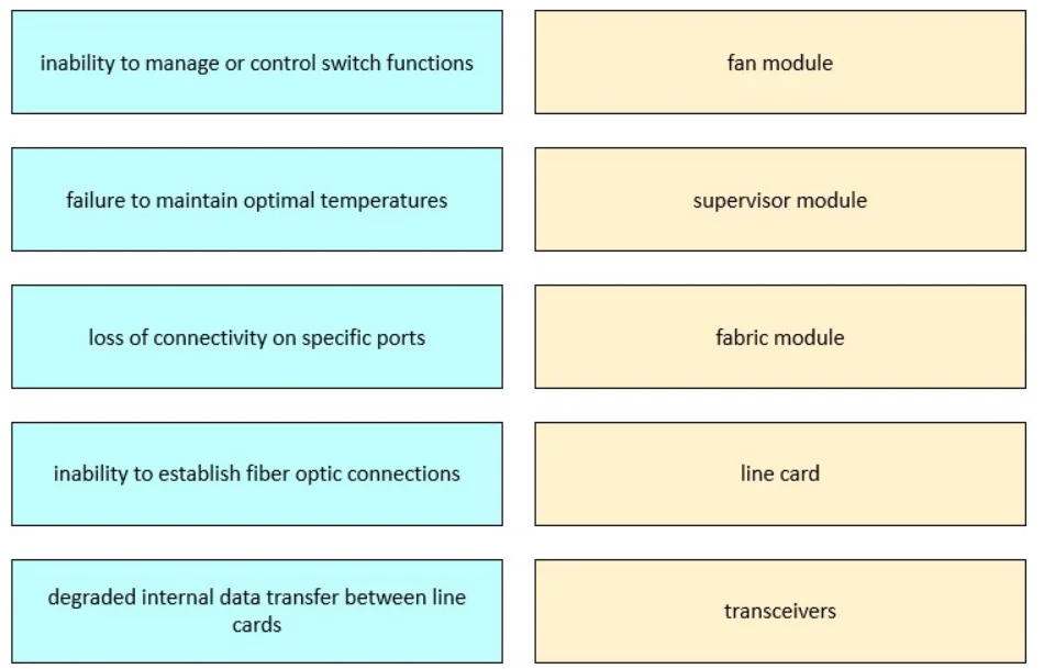
Answer Area
Drag items
Correct arrangement
- power supply modules
- fan tray assembly
- line card slots 1 and 2
- supervisor modules
- line card slots 5, 6, and 7
Explanation
MDS Chassis FRU Placement Explanation
This question maps Cisco MDS 9000-series (likely the MDS 9507, a 7-slot chassis) field-replaceable units to their physical positions on a chassis diagram. The numbered positions (1–5) represent labeled locations on the chassis, ordered roughly top-to-bottom or by functional grouping.
Item-by-Item Breakdown
1. Power Supply Modules → Position 1 Power supply bays occupy a dedicated section of the chassis, physically separate from the module slots. They appear first in the diagram because they are infrastructure-level components that must be identified independently of switching hardware. Common mistake: assuming power supplies are "inside" the slot numbering - they are not; they have their own bays.
2. Fan Tray Assembly → Position 2 The fan tray is likewise a standalone FRU adjacent to the power supplies. It sits outside the numbered module slots. Fans and PSUs are grouped together in diagrams because they are the two non-slot infrastructure FRUs. Mistake: placing the fan tray among the line card slots.
3. Line Card Slots 1 and 2 → Position 3 In the MDS 9507, slots 1 and 2 are the upper line card slots. Line cards occupy all non-supervisor slots (1, 2, 5, 6, 7). Slots 1–2 come before the supervisor slot range, so they appear above the supervisor modules in the physical layout.
4. Supervisor Modules → Position 4 Slots 3 and 4 are reserved exclusively for supervisor engines in the MDS 9507. They occupy the center of the chassis. This is a critical design point - supervisors cannot be placed in line card slots and vice versa. Mistake: thinking supervisors go at the top; they are in the center to allow symmetric cooling and access.
5. Line Card Slots 5, 6, and 7 → Position 5 These are the lower line card slots, below the supervisor modules. There are three of them (vs. two above), giving the MDS 9507 its 5 line card + 2 supervisor = 7-slot layout.
Key Takeaways
| Position | FRU | Why |
|---|---|---|
| 1 | Power supplies | Dedicated bay, not a numbered slot |
| 2 | Fan tray | Dedicated bay, adjacent to PSU |
| 3 | Line card slots 1–2 | Upper line card slots (above supervisor) |
| 4 | Supervisor modules | Center slots 3–4 (fixed, dedicated) |
| 5 | Line card slots 5–7 | Lower line card slots (below supervisor) |
Most common misconception: Students often place supervisor modules at position 1 (top), assuming they're the "most important" component. In the MDS 9507, supervisors are physically centered, flanked by line card slots above and below.
Topics
Community Discussion
No community discussion yet for this question.