
800-150 · Question #83
Drag and Drop Question Refer to the exhibit. Drag and drop the names of the field-replaceable units from the left onto the corresponding letters on the image of the Cisco Catalyst 9400 modular…
The correct answer is power supply modules; fan tray assembly; line card slots 1 and 2; supervisor modules; line card slots 5, 6, and 7. Cisco Catalyst 9400 Field-Replaceable Units (FRUs) - Placement Explanation The Catalyst 9400 is a modular chassis switch (e.g., the 9407R has 7 line card slots). The chassis has a fixed physical layout that dictates where each FRU lives. --- Position 1 - Power Supply Modules…
Question
Drag and Drop Question Refer to the exhibit. Drag and drop the names of the field-replaceable units from the left onto the corresponding letters on the image of the Cisco Catalyst 9400 modular switch. Answer:
Exhibit
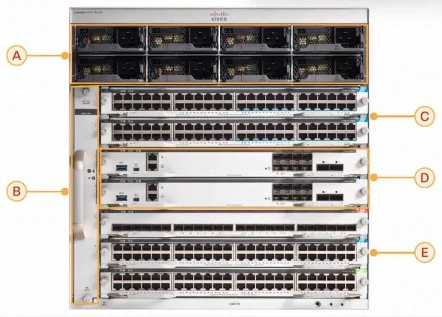
Answer Area
Drag items
Correct arrangement
- power supply modules
- fan tray assembly
- line card slots 1 and 2
- supervisor modules
- line card slots 5, 6, and 7
Explanation
Cisco Catalyst 9400 Field-Replaceable Units (FRUs) - Placement Explanation
The Catalyst 9400 is a modular chassis switch (e.g., the 9407R has 7 line card slots). The chassis has a fixed physical layout that dictates where each FRU lives.
Position 1 - Power Supply Modules
Why here: Power supplies are housed in a dedicated bay on the right side of the chassis, separate from the card slots. They are always at the "edge" of the chassis for hot-swap access without disturbing other components. The 9400 supports multiple PSUs for redundancy (N+1).
Common mistake: Students sometimes confuse power supplies with line cards because both slot in from the front. The PSU bay is clearly separated and narrower than line card slots.
Position 2 - Fan Tray Assembly
Why here: The fan tray sits at the bottom of the chassis (or rear, depending on the chassis variant). Airflow in the 9400 is front-to-back or side-to-side; the fans pull or push air across all modules. Placing the fan tray at the bottom keeps it accessible for hot-swap replacement without taking the chassis offline.
Common mistake: Confusing the fan tray with a line card slot - the fan tray spans the full width of the chassis and has a distinct pull-tab handle.
Position 3 - Line Card Slots 1 and 2
Why here: Slots 1 and 2 are the upper line card slots, physically located above the supervisor module bays. In the 9407R, the slot numbering goes top to bottom: 1, 2, [supervisor zone], 5, 6, 7.
Position 4 - Supervisor Modules
Why here: The supervisor engine occupies dedicated central slots (slots 3 and 4 in the 9407R). Cisco deliberately places the supervisor in the middle of the chassis for:
- Equal electrical path length to all line cards (above and below)
- Thermal balance - the supervisor generates significant heat and benefits from surrounding airflow
- Redundancy - dual supervisors can occupy slots 3 and 4 simultaneously
Common mistake: Many assume supervisors go in the top slot (like a "controller" at the top). They do not - they occupy fixed, numbered central slots and cannot be placed in standard line card slots.
Position 5 - Line Card Slots 5, 6, and 7
Why here: These are the lower line card slots, below the supervisor bays. The numbering skips 3 and 4 (reserved for supervisors), which is why the lower bank starts at 5. The 9407R therefore has 5 usable line card slots total (1, 2, 5, 6, 7) and 2 supervisor slots (3, 4).
Common mistake: Students often wonder why slots 3 and 4 are "missing" from the line card list - they aren't missing, they're the supervisor slots. The slot numbering is sequential top-to-bottom; supervisors just happen to own the middle slots.
Quick Summary Table
| Position | FRU | Physical Location |
|---|---|---|
| 1 | Power Supply Modules | Dedicated right-side bay |
| 2 | Fan Tray Assembly | Bottom of chassis |
| 3 | Line Card Slots 1 & 2 | Upper card slots (above supervisors) |
| 4 | Supervisor Modules | Central dedicated slots (3 & 4) |
| 5 | Line Card Slots 5, 6 & 7 | Lower card slots (below supervisors) |
The key insight is that the supervisor is always in the center, line cards flank it above and below, and the power/cooling components are in their own dedicated bays entirely outside the card-slot numbering scheme.
Topics
Community Discussion
No community discussion yet for this question.