
350-001 · Question #112
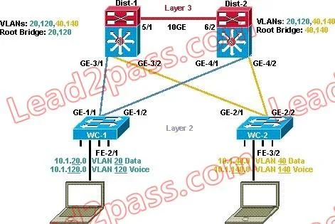
Refer to the exhibit. In the diagram, the switches are running IEEE 802.1s MST. Which ports are in the MST blocking state?
The correct answer is D. no ports are in the blocking state. Switches Dist-1 & 2 will have no ports in a blocking stating. However, switches WC-1 & 2 will have the secondary ports Ge1/2 & Ge2/1 in an Alternate/Blocking state as this will be backup ports for the root port. Ge1/2 & Ge2/1 will transition to a forwarding state and become…
Question
Refer to the exhibit. In the diagram, the switches are running IEEE 802.1s MST. Which ports are in the MST blocking state?
Exhibit
Options
- AGE-1/2 and GE 2/1
- BGE-1/1 and GE-2/2
- CGE-3/2 and GE 4/1
- Dno ports are in the blocking state
- EThere is not enough information to determine which ports are in the blocking state.
How the community answered
(43 responses)- A2% (1)
- B12% (5)
- C7% (3)
- D74% (32)
- E5% (2)
Explanation
Switches Dist-1 & 2 will have no ports in a blocking stating. However, switches WC-1 & 2 will have the secondary ports Ge1/2 & Ge2/1 in an Alternate/Blocking state as this will be backup ports for the root port. Ge1/2 & Ge2/1 will transition to a forwarding state and become root ports if ports Ge1/1 & Ge2/2 Multiple Spanning Tree (MST) is an IEEE standard inspired from the Cisco proprietary Multiple Instances Spanning Tree Protocol (MISTP) implementation. The main enhancement introduced by MST is that several VLANs can be mapped to a single spanning tree instance. This raises the problem of how to determine which VLAN is to be associated with which instance. More precisely, how to tag BPDUs so that the receiving devices can identify the instances and the VLANs to which each device applies. MST Configuration and MST Region Each switch running MST in the network has a single MST configuration that consists of these three attributes: 1. An alphanumeric configuration name (32 bytes) 2. A configuration revision number (two bytes) 3. A 4096-element table that associates each of the potential 4096 VLANs supported on the chassis to a given instance In order to be part of a common MST region, a group of switches must share the same configuration attributes. It is up to the network administrator to properly propagate the configuration throughout the region. Currently, this step is only possible by the means of the command line interface (CLI) or through Simple Network Management Protocol (SNMP). Other methods can be envisioned, as the IEEE specification does not explicitly mention how to accomplish that step. Note: If for any reason two switches differ on one or more configuration attribute, the switches are part of different regions. For more information refer to the Region Boundary section of this document.
Topics
Community Discussion
No community discussion yet for this question.