
200-301 · Question #893
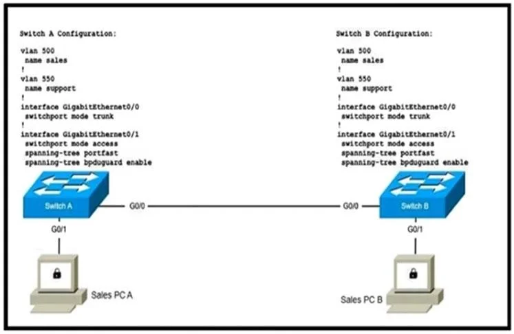
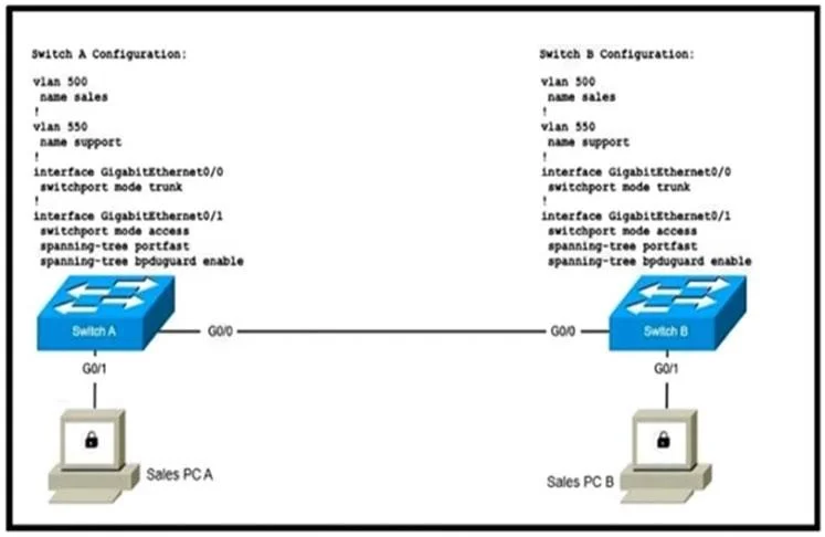
Refer to the exhibit. Two new switches are being installed. The remote monitoring team uses the support network to monitor both switches. Which configuration is the next step to establish a Layer 2…
The correct answer is A. SwitchA(config)#interface GigabitEthernet0/1. To enable Layer 2 communication between PCs on separate switches, the switches themselves must be connected, and their inter-switch link configured appropriately.
Question
Refer to the exhibit. Two new switches are being installed. The remote monitoring team uses the support network to monitor both switches. Which configuration is the next step to establish a Layer 2 connection between the two PCs?
Exhibits
Options
- ASwitchA(config)#interface GigabitEthernet0/1
- BSwitchA(config)#interface GigabitEthernet0/1
- CSwitchA(config)#interface GigabitEthernet0/0
- DSwitchA(config)#interface GigabitEthernet0/0
How the community answered
(60 responses)- A78% (47)
- B3% (2)
- C12% (7)
- D7% (4)
Why each option
To enable Layer 2 communication between PCs on separate switches, the switches themselves must be connected, and their inter-switch link configured appropriately.
The interfaces GigabitEthernet0/0 on both SwitchA and SwitchB are connected to end devices (PCs), serving as access ports. To establish Layer 2 communication between these PCs, the two switches must be physically connected to each other, typically using available interfaces like GigabitEthernet0/1, which would then be configured as a trunk link to carry traffic for the PCs' VLAN.
Choice B is incomplete and does not specify a meaningful configuration command beyond entering interface configuration mode, making it an invalid or insufficient step.
Configuring interface GigabitEthernet0/0 (SwitchA) is incorrect because it is already connected to PC1 and is likely an access port. This port is not used to establish the inter-switch link required for PC-to-PC communication across switches.
Choice D is incomplete and does not specify a meaningful configuration command beyond entering interface configuration mode for GigabitEthernet0/0, which is already connected to a PC.
Concept tested: Inter-switch link configuration
Source: https://www.cisco.com/c/en/us/td/docs/switches/lan/catalyst3850/software/release/3se/configuration_guide/b_layer_2_config_3850_3se_olcg/b_layer_2_config_3850_3se_olcg_chapter_0110.html
Topics
Community Discussion
No community discussion yet for this question.