N10-009 · Question #637
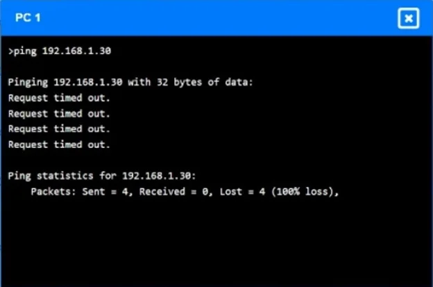
SIMULATION A network technician receives a ticket from an employee who is working on PC 1 but is unable to connect to the database server. The technician pings the database server from PC 1, but the…
High CPU utilization and a continuously changing MAC table on the switches, along with connectivity issues, indicate a Layer 2 loop in the network.
Question
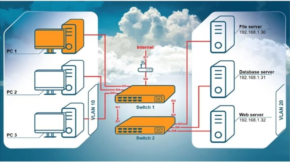
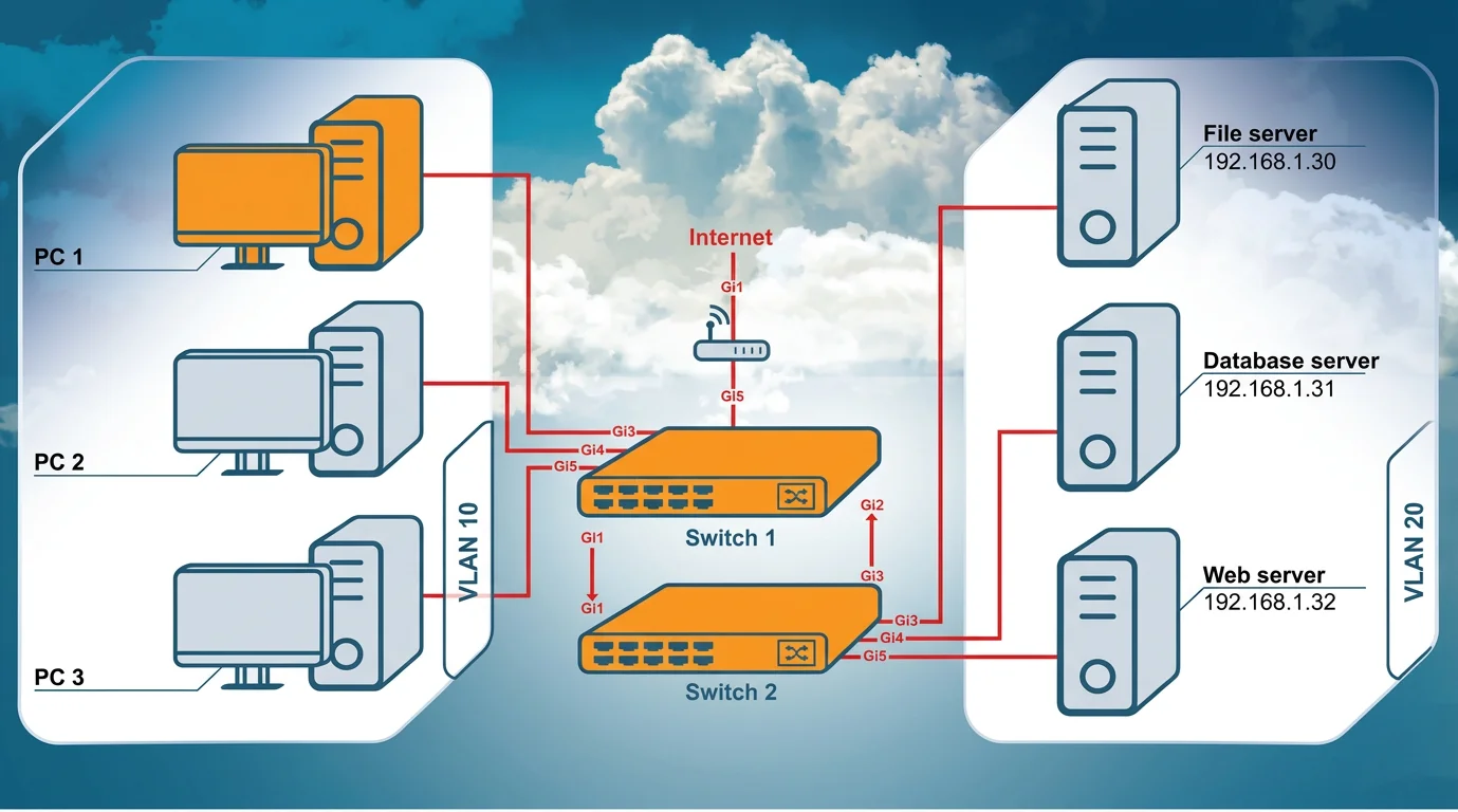
SIMULATION A network technician receives a ticket from an employee who is working on PC 1 but is unable to connect to the database server. The technician pings the database server from PC 1, but the request times out. After reviewing the utilization of Switch 1 and Switch 2, the technician finds high CPU utilization and sees that the MAC table is continuously changing. INSTRUCTIONS Configure Switch 1 and Switch 2 to remediate the employee s issue. Then, validate connectivity between PC 1 and the database server. Switch 1 and Switch 2 are already in configuration mode. Type help to view a list of available commands. If at any time you would like to bring back the initial state of the simulation, please click the Reset All button. Answer:
This simulation is based on typical CompTIA Network+ / Cisco-style switch commands used in the PBQ. The symptoms tell us:
- High CPU + constantly changing MAC table = switching loop
- The links between Switch 1 and Switch 2 (Gi1/1, Gi1/2, Gi2/3, Gi2/4 in the diagram) are not
configured as trunks
- VLAN 10 (PCs) and VLAN 20 (servers) must both traverse the link between switches
- The uplinks must be converted to trunk ports to carry both VLANs
Configure Switch 1 On Switch 1, convert the uplinks (Gi1/1 and Gi1/2 based on the diagram) to trunks:
interface gi1/1 switchport mode trunk switchport trunk allowed vlan 10,20 exit interface gi1/2 switchport mode trunk switchport trunk allowed vlan 10,20 exit Make sure the access ports in the PC side are VLAN 10 and the server side is VLAN 20:
interface gi1/4 switchport mode access switchport access vlan 10 exit interface gi1/5 switchport mode access switchport access vlan 10 exit Configure Switch 2 On Switch 2, configure the uplinks (Gi2/3 and Gi2/4 from the diagram) as trunks:
interface gi2/3 switchport mode trunk switchport trunk allowed vlan 10,20 exit interface gi2/4 switchport mode trunk switchport trunk allowed vlan 10,20 exit Configure server ports as VLAN 20:
interface gi2/1 switchport mode access switchport access vlan 20 exit interface gi2/2 switchport mode access switchport access vlan 20 exit interface gi2/5 switchport mode access switchport access vlan 20 exit Validate connectivity Go back to PC1 and ping the database server ping 192.168.1.31
Exhibits


Explanation
High CPU utilization and a continuously changing MAC table on the switches, along with connectivity issues, indicate a Layer 2 loop in the network.
Concept tested. Layer 2 loop detection and STP
Reference. https://www.cisco.com/c/en/us/support/docs/lan-switching/spanning-tree-protocol/10556-1.html
Community Discussion
No community discussion yet for this question.