N10-009 · Question #636
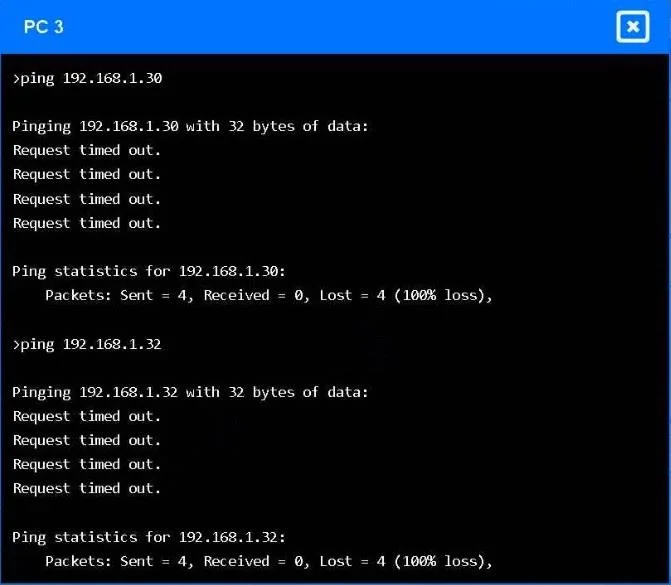
SIMULATION A network engineer receives reports that PC 3 cannot connect to either the file server or web server. The technician pings the web server and the file server from PC 3, but the request…
Explanation: VLAN Trunk Configuration to Restore Inter-VLAN Connectivity --- Overall Goal & Why This Approach is Correct PC 3 is in VLAN 10. The file server and web server are in VLAN 20. These are logically separate broadcast domains - devices in different VLANs cannot…
Question
SIMULATION A network engineer receives reports that PC 3 cannot connect to either the file server or web server. The technician pings the web server and the file server from PC 3, but the request times out. However, the technician is able to connect to the internet from PC 3. INSTRUCTIONS Click on Switch 1 and Switch 2 to configure and remediate the issue. Both devices are already in configuration mode. Type help to view a list of available commands. Then, click on PC 3 to validate its connectivity between the file server and the web server. The only VLANs available are currently configured within show vlan. If at any time you would like to bring back the initial state of the simulation, please click the Reset All button. Answer:
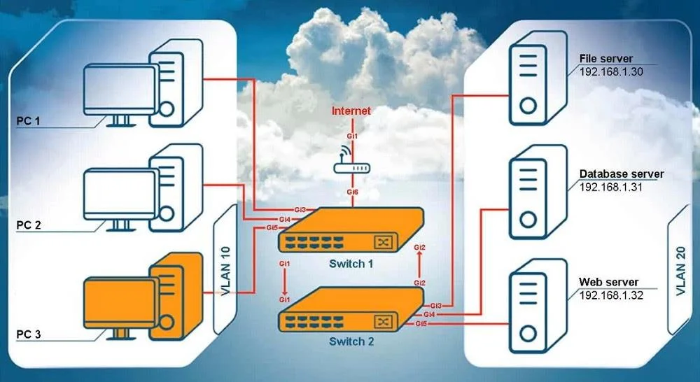
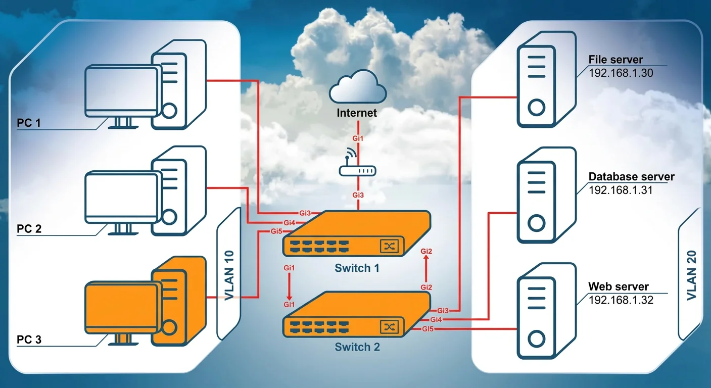
PC 3 is in VLAN 10, and the servers (file, database, web) are in VLAN 20. PC 3 can reach the internet, so its local VLAN is working. PC 3 cannot reach VLAN 20 servers, meaning the trunk between Switch 1 and Switch 2 is not passing VLAN 20. Configuration for Switch 1:
interface gi1 switchport mode trunk switchport trunk allowed vlan 10,20 end Configuration for Switch 2:
interface gi1 switchport mode trunk switchport trunk allowed vlan 10,20 end After entering these commands, return to PC 3 and validate connectivity. To validate connectivity from PC 3, you simply need to ping the servers again after applying the trunk configuration. On PC 3, run:
ping 192.168.1.30 ping 192.168.1.32 Successful validation means:
- You receive reply messages instead of “Request timed out.”
- Packet loss should be 0%.
If the trunk ports were configured correctly on both switches, both pings will succeed, confirming that:
PC 3 (VLAN 10) can now reach the servers (VLAN 20). Inter-VLAN connectivity through the switch trunk is restored.
Exhibits

Explanation
Explanation: VLAN Trunk Configuration to Restore Inter-VLAN Connectivity
Overall Goal & Why This Approach is Correct
PC 3 is in VLAN 10. The file server and web server are in VLAN 20. These are logically separate broadcast domains - devices in different VLANs cannot communicate directly without either a Layer 3 device (router/Layer 3 switch) doing inter-VLAN routing, OR a properly configured trunk link carrying both VLANs between switches.
The key diagnostic clue is: PC 3 can reach the internet but not the servers. This tells you:
- PC 3's NIC, IP config, and VLAN 10 are working fine (internet works)
- The problem is isolated to traffic crossing VLANs between switches
The inter-switch link (GigabitEthernet 1) is the only path between Switch 1 and Switch 2. If that link isn't configured as a trunk allowing both VLAN 10 and VLAN 20, traffic for one or both VLANs gets dropped. That's exactly what's happening here.
Step-by-Step Breakdown
Steps 1 & 6 - Click on Switch 1 / Switch 2
You must configure both switches because a trunk is a point-to-point link - both ends must agree on the mode and allowed VLANs. Configuring only one side leaves a mismatch, which still breaks connectivity.
Steps 2 & 7 - interface gi1
This enters interface configuration mode for GigabitEthernet 1, which is the uplink connecting the two switches. You must target this specific interface because trunk settings are per-interface. If you apply commands at the wrong interface, nothing changes on the inter-switch link.
Skipping this / wrong interface: Subsequent commands would modify the wrong port or fail entirely.
Steps 3 & 8 - switchport mode trunk
By default, switch ports operate in access mode, which only carries a single VLAN. Setting the port to trunk mode allows it to carry traffic for multiple VLANs simultaneously using 802.1Q tagging. Without this command, the port cannot pass traffic for more than one VLAN, regardless of what VLANs you "allow."
Skipping this: Even if you run
switchport trunk allowed vlan 10,20, it has no effect on an access port. The port still only carries one VLAN.
Steps 4 & 9 - switchport trunk allowed vlan 10,20
Trunk ports have an allowed VLAN list - a whitelist of which VLANs can traverse the trunk. By default, some implementations allow all VLANs, but others may have been previously restricted. This command explicitly permits both VLAN 10 (PC 3's VLAN) and VLAN 20 (servers' VLAN) on the trunk.
Skipping this: If VLAN 20 is not in the allowed list, the trunk drops all VLAN 20 frames - servers remain unreachable even with trunk mode active. If VLAN 10 were also missing, PC 3 would lose internet access too.
Steps 5 & 10 - end
This exits interface configuration mode and returns to privileged EXEC mode, saving the configuration context. It's good practice to exit before validating, and some platforms only apply certain settings cleanly upon exiting the config context.
Skipping this: You risk leaving the switch in config mode, and validation commands like
showmay behave unexpectedly or be unavailable.
Step 11 - Click on PC 3
You must move to PC 3's CLI to test from the perspective of the affected device. Testing from the switch itself (e.g., ping from the switch) wouldn't simulate the actual user traffic path through both VLANs.
Steps 12 & 13 - ping 192.168.1.30 and ping 192.168.1.32
These validate the fix end-to-end. A successful ping (0% packet loss, replies received) confirms that:
- VLAN 10 traffic leaves PC 3
- It traverses the trunk on Switch 1 (tagged as VLAN 10)
- Switch 2 receives it and routes/forwards it to VLAN 20
- The server replies traverse the same trunk back
If either ping still times out after configuration, the trunk is still misconfigured on one or both switches - re-check the allowed VLAN list and trunk mode on both ends.
What Happens If Steps Are Done Out of Order
| Mistake | Result |
|---|---|
| Configure only one switch | Trunk mismatch - link may negotiate to access mode or drop VLAN-tagged frames |
Run allowed vlan before mode trunk | Command may apply but have no effect on an access port |
Skip end before pinging | May get unexpected results depending on platform behavior |
| Ping from the switch instead of PC 3 | Doesn't validate the actual user traffic path |
Memory Tip
Think of it as "Mode first, then Filter" - on each switch, you first establish the trunk (mode trunk), then define what crosses it (allowed vlan). And always remember: both ends of a trunk must match, just like both ends of a phone call need to be connected.
The acronym ITEM can help recall the interface config sequence:
- I -
interface gi1 - T -
switchport mode trunk - E -
switchport trunk allowed vlan - M -
end(exit/M for "move on")
Topics
Community Discussion
No community discussion yet for this question.