
HP2-Z30 · Question #39
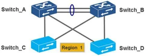
Refer to the network exhibit. Switch_A and Switch_B are HP Comware switches currently in the same MSTP region with the following MSTP configuration: Region name: HP Revision number 1 Instance…
Sign in or unlock HP2-Z30 to reveal the answer and full explanation for question #39. The question stem and answer options stay visible for context.
Question
Refer to the network exhibit. Switch_A and Switch_B are HP Comware switches currently in the same MSTP region with the following MSTP configuration:
Region name: HP Revision number 1 Instance 1:VLANs 10 and 11 Instance 2: VLANs 12 and 13 Instance 0: VLANs 1-9 and 14-4094 MSTP is operating correctly on Switch_A and Switch_B. Switch_C and Switch_D are new Comware switches and have been added to the network. The links between the switches are trunks, where VLAN 1 is the PVID and all other VLANs are permitted on the trunks. The only STP command executed on the two new switches is stp enable. Based on this information, what is the resulting Layer 2 topology?
Exhibit
Options
- AAll uplinks are blocked until the new switches have MSTP configured correctly.
- BA Layer 2 loop will result, creating a broadcast storm,
- COnly one uplink from each new switch will be utilized.
- DBoth uplinks from the new switches are utilized but load sharing is inefficient
Unlock HP2-Z30 to see the answer
You've previewed enough free HP2-Z30 questions. Unlock HP2-Z30 for full answers, explanations, the timed quiz mode, progress tracking, and the master PDF. Question stem and options stay visible so you can still see what's on the exam.