
Huawei
H12-831_V1.0 · Question #92
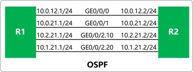
In the OSPF network shown in the figure, R1 and R2 are connected by four links. OSPF is enabled on the Loopback0 interface of R2. The "maximum load-balancing 3" command is configured in the OSPF…
The correct answer is C. GE0/0/0. See the full explanation below for the reasoning.
Question
In the OSPF network shown in the figure, R1 and R2 are connected by four links. OSPF is enabled on the Loopback0 interface of R2. The "maximum load-balancing 3" command is configured in the OSPF process of R1. Which of the following is the outbound interface from R1 to the Loopback0 interface of R2?
Exhibit
Options
- AGE0/0/2.20
- BGE0/0/1
- CGE0/0/0
- DGE0/0/2.10
How the community answered
(40 responses)- A3% (1)
- B5% (2)
- C80% (32)
- D13% (5)
Community Discussion
No community discussion yet for this question.