800-150 · Question #58
800-150 Question #58: Real Exam Question with Answer & Explanation
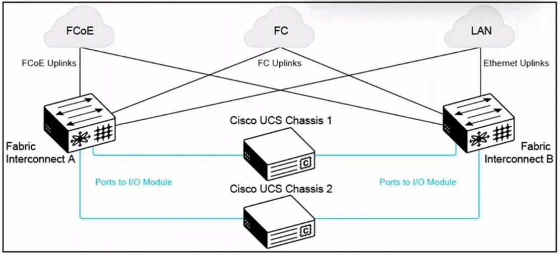
The correct answer is A. Redundancy is achieved through dual fabric interconnects, providing separate paths for FCoE, FC,. In the provided Cisco UCS architecture diagram, the infrastructure consists of: Two Fabric Interconnects (A and B), each connecting to: Fibre Channel (FC) FCoE (Fibre Channel over Ethernet) Both Fabric Interconnects are independently connected to both Cisco UCS Chassis 1 and 2 th
Question
Exhibit
Options
- ARedundancy is achieved through dual fabric interconnects, providing separate paths for FCoE, FC,
- BRedundancy is limited to the uplink connections, with no failover capabilities between the fabric
- CThe system uses a single point of connectivity, relying on internal redundancy within each UCS
- DRedundancy is implemented at the chassis level only, with chassis 1 acting as a backup for
Explanation
In the provided Cisco UCS architecture diagram, the infrastructure consists of: Two Fabric Interconnects (A and B), each connecting to: Fibre Channel (FC) FCoE (Fibre Channel over Ethernet) Both Fabric Interconnects are independently connected to both Cisco UCS Chassis 1 and 2 through I/O Modules (IOMs). This is the classic active-active UCS design, providing full path redundancy for all traffic types: LAN uplinks are handled separately by Fabric Interconnect B. SAN traffic is distributed through FC uplinks and FCoE uplinks via Fabric Interconnects A and B. Each server in the chassis can fail over its traffic to the alternate fabric if one interconnect fails. This architecture guarantees no single point of failure, which is essential in mission-critical environments like data centers and enterprise server farms.
Community Discussion
No community discussion yet for this question.